【 Rated Voltage of Transformers 】
The rated voltage of a transformer is the specific voltage level at which the transformer is designed to operate efficiently and safely. Operating a transformer at voltages that are too high or too low can lead to inefficiencies, overheating, and reduced lifespan. Therefore, it is crucial to ensure that the input and output voltages match the transformer's rated values. If necessary, voltage regulation devices can be used to maintain the correct operating voltage.
【 Applications of Small Transformers 】
Small transformers, typically with a capacity of less than 1 kVA, are commonly single-phase units used in a variety of applications:
-
- Control Power Transformers: Provide power for control circuits in electrical equipment.
- Power Supply Transformers for Electronic Devices: Supply stable DC or AC power to electronic components and circuits.
- Safety Lighting Transformers: Reduce voltage to safe levels for low-voltage lighting systems, ensuring user safety.
【 Losses in Transformers During Operation 】
Transformers experience two main types of losses during operation:
-
Core Losses (Iron Losses): These losses occur due to the alternating magnetic field in the core, causing hysteresis loss and eddy current loss. Hysteresis loss results from the repeated magnetization and demagnetization of the core material, while eddy current loss is caused by circulating currents induced within the core. Core losses are present even when there is no load on the transformer.
-
Winding Losses (Copper Losses): These losses are due to the resistance of the wire in the windings. When current flows through the primary and secondary windings, some energy is lost as heat. Copper losses increase with the square of the current, so they are more significant under heavy load conditions.
【 How to Choose a Transformer 】
Selecting the right transformer involves several key considerations:
- Purpose: Determine whether the transformer will be used for stepping up or stepping down voltage.
- Phase Configuration: Identify if the application requires a single-phase or three-phase transformer.
- Operating Environment: Choose the appropriate cooling method based on the installation environment (e.g., air-cooled for indoor use, oil-immersed for outdoor use).
- Material of Windings: Decide between copper or aluminum windings based on performance requirements and budget constraints. Copper windings generally offer better conductivity and efficiency but are more expensive.
- Rated Parameters: Select a transformer based on its rated voltage, rated current, and rated capacity (kVA or MVA). Ensure that these parameters match the specific needs of your application.
【 Grounding of the Transformer Core 】
In power transformers, the core must be grounded at one point to ensure safe and reliable operation. Proper grounding serves several important functions:
- Elimination of Floating Potential: Without grounding, the core can develop a floating potential relative to ground, which may lead to partial discharges or insulation breakdown. Grounding the core at a single point eliminates this risk.
- Prevention of Discharge: A single-point ground connection prevents the core from experiencing intermittent discharge to ground, which can occur if the core is not properly grounded. This discharge can cause damage to the insulation and reduce the transformer's lifespan.
- Safety: Grounding the core ensures that any fault currents are safely conducted to ground, reducing the risk of electric shock and equipment damage.
 When the transformer core has more than one grounding point, an uneven potential between these points can cause circulating currents to form between the grounding points. This leads to multiple grounding faults in the core, resulting in localized overheating. In severe cases, the increased local temperature can trigger the light gas relay (indicating a minor fault), and if not addressed, it can escalate to activate the heavy gas relay, causing the transformer to trip and shut down. Such faults can significantly reduce the lifespan of the transformer and pose a serious safety risk.
【 Differences Between Neutral Point, Earth Point, and Earth Wire 】
- Neutral Point: The common connection point where the three-phase windings' start or end terminals are joined together is referred to as the neutral point of the power source.
- Earth Point (Zero Point): When the neutral point is connected to the grounding system with a good electrical connection, this point is then called the earth point or zero point.
- Earth Wire (Zero Line): The conductor that extends from the earth point is known as the earth wire or zero line. This wire provides a reference point for the electrical system and helps ensure safe operation by maintaining a stable potential difference.
【 Differences Between Energy Meters and Power Meters 】
- Energy Meter: An energy meter can simultaneously display and record various parameters such as active energy, reactive energy, power factor, load curves, and the times of maximum and minimum loads. It provides comprehensive data on the electrical consumption and quality.
- Power Meter: A power meter, on the other hand, typically displays only the instantaneous active or reactive power. It provides a single value at a given moment but does not offer the detailed historical or cumulative data that an energy meter does.
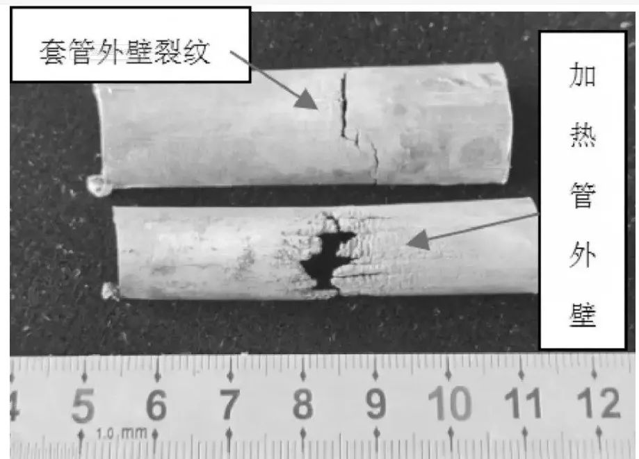
【 Hazards of Bushing Cracks 】
Cracks in transformer bushings can significantly reduce the insulation strength, leading to further degradation of the insulation material. Over time, this can result in complete insulation failure. Additionally, water that enters the cracks can freeze and expand during cold weather, potentially causing the bushing to crack further or even rupture. This can lead to serious safety hazards and equipment damage, necessitating immediate attention and repair to prevent catastrophic failure.
【 Role of the Central Signal System 】
The Central Signal System in a substation is designed to provide both accident signals and warning signals. It is typically installed on the central signal panel in the main control room of the substation. The system operates as follows:
- Accident Signals: These are activated when any circuit breaker in the substation trips due to a fault. The accident signal alerts the operators to an immediate issue that requires urgent attention.
- Warning Signals: These are triggered when abnormal operating conditions occur, such as equipment malfunctions or failures in the operating power supply. Warning signals indicate potential problems that need to be addressed to prevent further issues.
Both types of signals include audible alarms and visual indicators (lights). The audible signals draw the attention of the on-duty personnel, while the visual signals help them identify the nature and location of the fault.
【 Internal Overvoltage 】
Internal overvoltage occurs due to sudden changes in the system's state caused by operations, accidents, or other factors. This can result in a transition from one stable state to another, during which dangerous overvoltages may appear. These overvoltages can pose significant risks to the system's components and must be carefully managed to prevent damage.
【 Function of High-Voltage Circuit Breakers 】
High-voltage circuit breakers play a critical role in electrical systems, serving two primary functions:
- Control Function:
- When the circuit experiences no-load current or high load currents, the circuit breaker can open or close the circuit as needed. This allows for precise control over the power flow, ensuring that the system operates within safe limits.
- Protection Function:
- In the event of a fault, such as a short circuit or open circuit, the circuit breaker can quickly interrupt the fault current. This protective feature prevents damage to the system and ensures the safety of both equipment and personnel.


