Open Type:
This is a common form where the core is directly exposed to the atmosphere. It is suitable for relatively dry and clean indoor environments (relative humidity should not exceed 85% at 20°C). Typically, it uses either natural air cooling or forced air cooling.
Enclosed Type:
The core is housed within a sealed enclosure, isolated from direct contact with the atmosphere. Due to poor heat dissipation and sealing conditions, this type is mainly used in mining applications and is explosion-proof.
Cast-Resin Type:
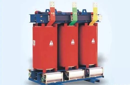
The main insulation is made using epoxy resin or other resins. It has a simple structure, small size, and is suitable for transformers with smaller capacities.
The cooling methods for dry-type transformers are divided into:
Impregnated Air-Insulated Dry-Type Transformers:
Rarely used today. Insulation materials for windings are selected based on different thermal resistance grades, forming B-class, F-class, or H-class insulated dry-type transformers.
Epoxy Resin Cast Dry-Type Transformers:
Insulation materials include polyester resin and epoxy resin. Most cast-insulated power transformers currently use epoxy resin.
Wound Insulation Dry-Type Transformers:
A type of resin-insulated transformer, but fewer manufacturers produce this type.
Hybrid Insulation Dry-Type Transformers:
Fire Safety:
Dry-type transformers avoid the risk of fire or explosion caused by transformer oil faults. Their insulation materials are flame-retardant, so even if a fault occurs or an external fire source is present, the fire will not spread.
Maintenance-Free Operation:
Unlike oil-immersed transformers, dry-type transformers do not suffer from oil leakage or aging issues. Maintenance and repair work are significantly reduced, and in some cases, they can be maintenance-free.
Compact Design:
Dry-type transformers are typically installed indoors. For special requirements, they can also be designed for outdoor use. They can be installed alongside switchgear in the same room, saving space.
Fewer Components:
Dry-type transformers have no oil-related accessories such as oil tanks, safety vents, or numerous valves, eliminating sealing problems.
Pre-Installation Inspection:
Check if the packaging is intact. After unpacking, verify that the nameplate data matches the design requirements, ensure all factory documents are complete, inspect the transformer for damage or displacement, and check for any loose or damaged components. Verify spare parts for completeness.
Transformer Installation:
Inspect the foundation for levelness and ensure there are no voids under the steel plates to guarantee good seismic and sound-absorption performance. Use rollers to move the transformer to the installation position, then precisely adjust it to the design location. Weld four short channel steels to the embedded steel plates near the transformer base to prevent movement during operation.
Transformer Wiring:
Ensure minimum distances between live parts and between live parts and ground, especially for cables connected to high-voltage windings. Large-current low-voltage busbars should be independently supported and not directly connected to transformer terminals to avoid excessive mechanical stress. For currents exceeding 1000A, a flexible connection must be used between the busbar and transformer terminals to accommodate thermal expansion/contraction and isolate vibrations. Electrical connections must maintain necessary contact pressure using elastic elements like spring washers. Tighten bolts using a torque wrench, referring to manufacturer-provided torque values.
Transformer Grounding:
The grounding point is located on the low-voltage side base, marked with a dedicated grounding bolt. Grounding must be securely connected to the protective grounding system. If the transformer has a housing, it should also be reliably grounded. For three-phase four-wire systems, the neutral line must be grounded.
Pre-Operation Inspection:
Check for loose fasteners, correct electrical connections, and proper insulation distances. Ensure there are no foreign objects near the transformer and that the coil surfaces are clean.
Pre-Operation Testing:
Trial Operation:
After thorough inspection, energize the transformer for trial operation. During this period, monitor for abnormal sounds, odors, overheating, or vibration. Ensure good ventilation. Note the following:
Phase Loss:
If a phase is missing, the transformer may remain silent until the third phase is connected. Causes include power loss, blown fuses, or broken leads.
Tap Changer Issues:
Incomplete tap changer operation causes a "buzzing" sound, potentially blowing high-voltage fuses. Poor contact results in sparking noises.
Foreign Objects or Loose Core Bolts:
Foreign objects or loose bolts cause knocking or whistling sounds. These issues do not affect operation but should be addressed during downtime.
High-Voltage Bushing Contamination or Damage:
Dirty or cracked bushings cause surface flashover, producing hissing sounds or visible sparks at night.
Core Grounding Break:
A broken core ground produces faint sparking sounds.
Internal Discharge:
Arcing sounds indicate discharge to the housing through air or oil. Insufficient insulation requires inspection and reinforcement.
External Line Faults:
Line breaks or short circuits produce buzzing or roaring sounds.
Overload:
Severe overload causes a deep humming sound.
High Voltage:
Excessive voltage increases excitation and produces sharp, loud noise.
Winding Short Circuits:
Layer or turn-to-turn short circuits cause boiling-like sounds.
Cooling Fans:
Abnormal fan noises may result from foreign objects or poor-quality fans. Clean or replace fans as needed.
Transformer Housing:
Vibrations from poorly fixed housings produce noise. Add rubber pads between the housing and base to reduce sound transmission.
Room Acoustics:
Echoes from walls can amplify noise. Adjust transformer placement or install sound-absorbing materials.
Floor or Support Issues:
Weak floors or supports increase vibrations. Reinforce the installation site to reduce noise.
Load-Based Selection:
Environment-Based Selection: