Any electrical equipment, including power transformers, incurs losses during prolonged operation, primarily divided into copper losses (due to the windings) and iron losses (due to the core).
Copper Loss in Transformers
【 Definition and Principle 】
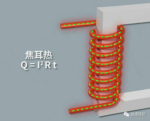
Copper plays a crucial role in transformers, with the windings typically made of copper conductors. The copper loss in a transformer refers to the power dissipated as heat due to the resistance of these copper conductors. Also known as load loss, copper loss is a variable loss that changes with the load. When a transformer operates under load, current flowing through the windings encounters electrical resistance, resulting in resistive losses. According to Joule's Law, this resistance generates Joule heating, and the power loss increases with the square of the current. Therefore, copper loss is proportional to the square of the current and is independent of the voltage. Since it varies with the current, copper loss (load loss) is a variable loss and constitutes a significant portion of the transformer's operational losses.
【 Factors Affecting Copper Loss 】
- Current Magnitude: As mentioned, copper loss is directly proportional to the square of the current. Thus, the magnitude of the current is a key factor influencing copper loss.
- Winding Resistance: The size of the winding resistance directly impacts copper loss. Higher resistance leads to higher copper loss.
- Number of Winding Layers: More layers in the windings increase the path length for current flow, thereby increasing resistance and copper loss.
- Switching Frequency: The effect of switching frequency on copper loss depends on the transformer's distributed parameters and load characteristics. When the load and distribution parameters exhibit inductive behavior, copper loss decreases with increasing switching frequency; conversely, when they exhibit capacitive behavior, copper loss increases with higher switching frequency.
- Temperature Effects: Load losses are influenced by the transformer's temperature. The leakage flux caused by load current can induce eddy currents within the windings, leading to additional losses. Additionally, stray losses occur in the metal parts surrounding the windings.
【 Calculation Methods 】
There are two primary formulas for calculating copper loss:
- Based on Rated Current and Resistance:
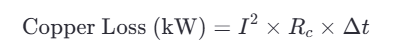
Where:
I is the rated current of the transformer,
Rc is the resistance of the copper conductor,
Δt is the operating time of the transformer.
- Based on Rated Current and Total Copper Resistance

Where:
I is the rated current of the transformer,
R is the total copper resistance of the transformer, which can be calculated as:

Where:
R1 is the copper resistance on the primary side,
R2 is the copper resistance on the secondary side.
【 Methods to Reduce Copper Loss 】
- Increase Winding Cross-Sectional Area: By increasing the cross-sectional area of the windings, the conductor resistance is reduced, effectively lowering copper losses.
- Use High-Quality Conductive Materials: Employing materials like copper foil or aluminum foil with lower resistivity can reduce winding resistance.
- Minimize Light Load Operation Time: Limiting the time the transformer operates under light load conditions can help reduce copper losses.
Iron Loss in Transformers
【 Definition and Principle 】
Unlike copper loss, iron loss in transformers is not influenced by the windings or the magnitude of the current. As the name suggests, iron loss is associated with the core of the transformer. It is also known as no-load loss because it occurs regardless of whether the transformer is operating at full load or zero load, making it a fixed loss. However, the power loss decreases with reduced magnetic field strength under load conditions.
Iron loss primarily consists of two components: hysteresis loss and eddy current loss.
【 Classification 】
Hysteresis loss arises from the magnetic properties of the core material. When the transformer operates based on electromagnetic induction, the magnetic flux flows through the core. The core exhibits magnetic reluctance, similar to how conductors exhibit electrical resistance, leading to heat generation. This heat generation is referred to as hysteresis loss. The energy required to reverse the magnetization of the core material during each cycle of alternating current contributes to this loss.
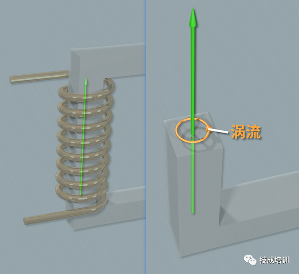
Eddy current loss occurs when the primary winding is energized, and the resulting magnetic flux flows through the core. Since the core itself is a conductor, it induces electric potentials perpendicular to the magnetic field lines. These potentials form closed loops within the cross-section of the core, creating circulating currents known as eddy currents. The power dissipated by these eddy currents is called eddy current loss. To minimize this effect, the core is typically made from thin laminations, which increase the resistance to eddy currents, thereby reducing the loss.
【 Factors Affecting Iron Loss 】
- Operating Voltage and Frequency:
Iron loss is influenced by the transformer's operating voltage and frequency. These factors affect the magnetic field strength and hysteresis phenomena within the core. Higher voltage and frequency generally lead to increased iron loss.
The magnetic properties of the core material play a significant role in determining the magnitude of iron loss. Poorly chosen materials with high hysteresis can significantly increase losses. Materials with low hysteresis, such as grain-oriented silicon steel, are preferred to minimize iron loss.
The manufacturing process of the transformer, including the lamination technique and insulation treatment of the core, can impact iron loss. Proper stacking of core laminations and effective insulation between layers help reduce both hysteresis and eddy current losses.
【 Calculation Methods 】
- Based on Rated Current and Hysteresis/Resistance Losses
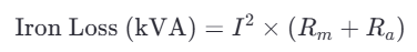
Where:
I is the rated current of the transformer,
Rm is the hysteresis loss in the core,
Ra is the resistive loss in the core.
- Based on Constants, Flux Density, and Operating Frequency:
Where:
Piron is the iron loss,
Kf is a constant specific to the core material,
Bm is the maximum flux density,
f is the operating frequency of the transformer.
【 Methods to Reduce Iron Loss 】
-
Select High-Quality Core Materials:
- Using core materials with low hysteresis, such as grain-oriented silicon steel, can significantly reduce iron loss.
-
Optimize Manufacturing Processes:
- Improving the lamination technique, insulation treatment, and overall manufacturing process can help minimize both hysteresis and eddy current losses.
-
Optimal Design:
- During the design phase, optimizing the transformer's structure and selecting appropriate parameters can further reduce iron loss. For example, using thinner laminations and designing for lower magnetic field strengths can be effective strategies.


