1. Introduction
Power transformers are critical assets in electrical transmission and distribution networks, designed to transfer electrical energy efficiently between voltage levels with minimal losses. Among the key performance indicators that define a transformer’s efficiency, thermal behavior, and system compatibility are:
- No-load loss (core loss)
- Load loss (copper loss)
- Impedance voltage (short-circuit impedance)
These parameters are not only essential for evaluating energy efficiency but also crucial for short-circuit studies, voltage regulation calculations, protection coordination, and lifecycle cost analysis. This article provides a comprehensive technical overview of their physical origins, standard calculation methods, measurement procedures, and engineering relevance.
2. No-Load Loss (Core Loss)
2.1 Definition and Origin
No-load loss ( P0 ) is the power consumed by a transformer when it is energized at rated voltage and frequency on the primary side while the secondary winding is open-circuited. Under these conditions, the transformer draws a small excitation current (typically 1–5% of full-load current), which sustains the magnetic flux in the core.
The no-load loss primarily consists of:
- Hysteresis loss: Energy dissipated due to repeated magnetization and demagnetization of the core material.
- Eddy current loss: Circulating currents induced in the core laminations by the alternating magnetic field.
Both losses depend on:
- Core material (e.g., grain-oriented silicon steel)
- Lamination thickness
- Operating frequency ( f )
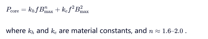
- Peak flux density ( Bmax )
Empirically, core loss can be approximated by the Steinmetz equation:
2.2 Measurement and Standard Practice
Per IEC 60076-1 and IEEE C57.12.90, no-load loss is measured during the open-circuit test:
- Rated voltage and frequency applied to one winding (usually HV)
- Other winding left open
- Input power measured using precision wattmeters
The result is corrected to reference temperature (usually 20°C) and reported as P0 in watts or kilowatts.
2.3 Engineering Significance
- Dominates total loss at light loads; critical for energy efficiency standards (e.g., DOE 2016, EU Ecodesign)
- Directly impacts standby energy consumption and operational cost over the transformer’s lifetime
- Used in total ownership cost (TOC) calculations
3. Load Loss (Copper Loss)
3.1 Definition and Origin
Load loss ( Pk ) is the power dissipated in the windings due to resistive heating when the transformer carries load current. It is proportional to the square of the load current and includes:
- DC resistance loss ( I2R )
- Additional losses due to:
- Skin effect and proximity effect in conductors
- Eddy currents in windings, clamping structures, and tank walls
- Stray losses from leakage flux
Thus, total load loss is expressed as:
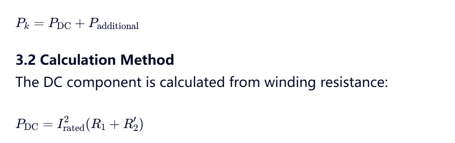
where R1 and R2′ are primary and referred secondary resistances at reference temperature (usually 75°C or 85°C per standard).
Additional losses are estimated using empirical factors or finite element analysis (FEA). Standards typically apply a stray loss factor (e.g., 1.1–1.3× DC loss) unless detailed design data is available.
3.3 Measurement
Load loss is determined via the short-circuit test:
- One winding shorted
- Reduced voltage applied to the other until rated current flows
- Input power measured → equals total load loss at rated current
Results are corrected to standard reference temperature (e.g., 75°C for mineral oil-filled units per IEEE C57.12.00).
3.4 Engineering Relevance
- Dominates losses at full load; key for thermal design and cooling system sizing
- Critical for efficiency certification (e.g., NEMA TP-1, IEC 60076-20)
- Influences voltage regulation and system stability
4. Impedance Voltage (Short-Circuit Impedance)
4.1 DefinitionImpedance voltage ( uk or Zk% ) is the percentage of rated voltage that must be applied to one winding to circulate rated current through the windings when the other winding is short-circuited. It represents the transformer’s equivalent series impedance: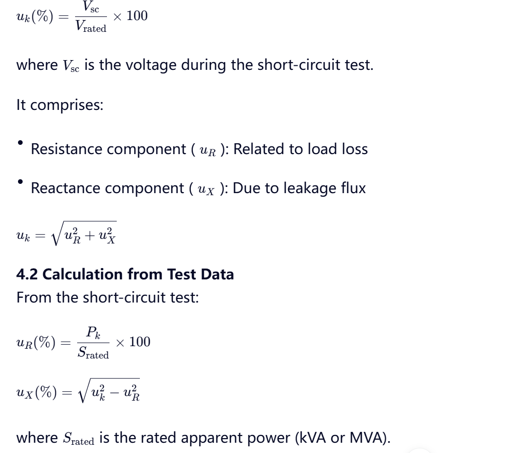
4.3 System-Level Importance
- Determines fault current magnitude: Ifault≈uk/100Irated
- Affects voltage regulation: ΔV≈I(Rcosϕ+Xsinϕ)
- Influences parallel operation compatibility: Transformers must have closely matched uk values (<±10%) to share load proportionally
- Impacts motor starting voltage dip and protective device coordination
Typical impedance values:
- Distribution transformers (≤2.5 MVA): 4–6%
- Power transformers (>10 MVA): 8–12%
5. Integration in Efficiency and Economic Analysis
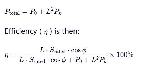
Total transformer loss at any load factor ( L ) is:
For Total Ownership Cost (TOC) evaluation, utilities assign A and B factors to monetize no-load and load losses:
TOC=Purchase Price+A⋅P0+B⋅Pk
This approach incentivizes high-efficiency designs beyond nameplate ratings.
6. Standards and Testing Protocols
Key international standards governing these parameters include:
- IEC 60076-1: General specifications
- IEC 60076-8: Test code for losses and impedance
- IEEE C57.12.90: Test procedures for liquid-immersed transformers
- IEEE C57.12.00: General requirements
All require correction of measured losses to standard reference temperatures and inclusion of auxiliary losses (e.g., cooling fans, pumps) where applicable.
7. Conclusion
No-load loss, load loss, and impedance voltage are fundamental electrical characteristics that define a transformer’s performance, efficiency, and interaction with the power system. Accurate calculation and measurement of these parameters—guided by international standards—are essential for:
- Selecting optimal transformers for specific applications
- Ensuring grid reliability and protection coordination
- Meeting regulatory efficiency mandates
- Minimizing long-term operational costs
As global emphasis on energy sustainability intensifies, precise understanding and optimization of these losses will remain central to the design, procurement, and operation of modern power transformers.
Note: For dry-type, amorphous metal-core, or high-efficiency transformers, loss components may differ significantly due to advanced materials and construction techniques.


