Introduction
Power transformers are critical components in electrical power systems, serving as the backbone for voltage transformation, energy transmission, and distribution. Understanding their core technologies, structural principles, and operation & maintenance (O&M) essentials is vital for ensuring reliable and efficient performance.
1. Core Technologies of Power Transformers
1.1 Magnetic Core Design
The magnetic core is a fundamental component of a transformer, typically constructed from laminated silicon steel sheets to minimize eddy current losses and hysteresis losses. The core design determines the transformer's efficiency, thermal performance, and ability to handle magnetization characteristics under varying load conditions.
- Key Considerations:
- Flux density and saturation levels.
- Core material properties (e.g., grain-oriented silicon steel).
- Lamination thickness and insulation coatings to reduce losses.
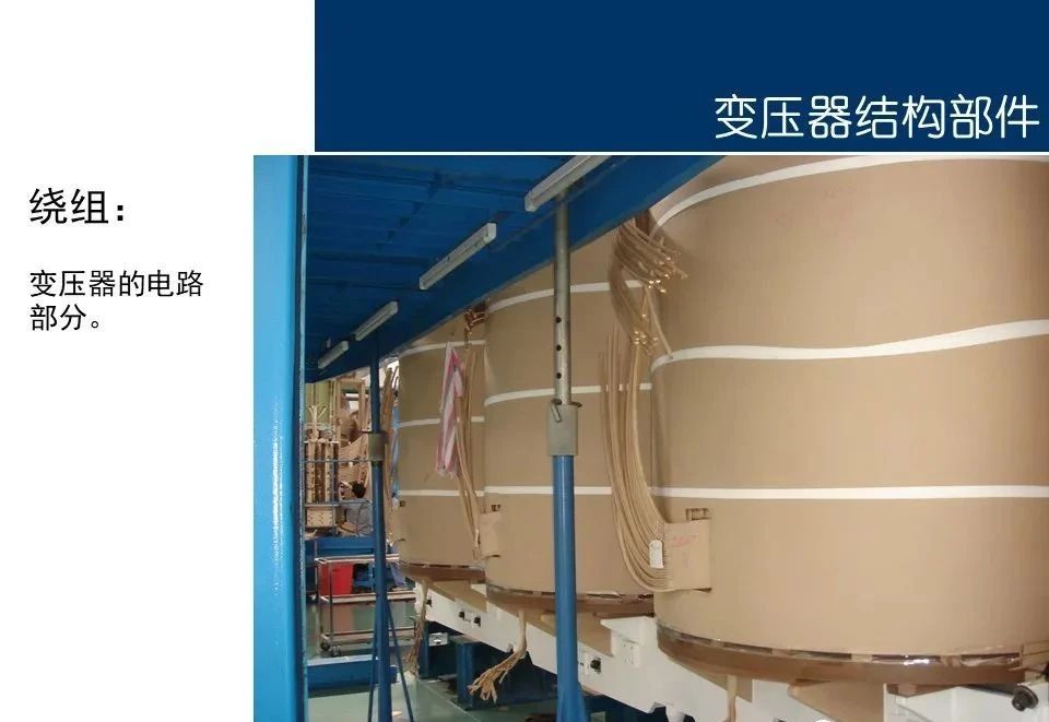
1.2 Winding Configuration
Transformer windings are responsible for electromagnetic induction, transferring energy between the primary and secondary sides. Windings are typically made of copper or aluminum conductors and are insulated to withstand high voltages and temperatures.
-
Types of Windings:
- Concentric windings (layered or disk-type).
- Foil windings (used in low-voltage applications).
- Interleaved windings (for reduced leakage reactance).
-
Key Parameters:
- Insulation materials and clearance requirements.
- Thermal dissipation and cooling mechanisms.
- Short-circuit withstand capability.
1.3 Cooling Systems
Efficient cooling is essential to maintain safe operating temperatures and prevent overheating. Transformers employ various cooling methods based on their size, application, and environmental conditions.
- Cooling Methods:
- ONAN (Oil Natural Air Natural): Self-cooling using natural convection of oil and air.
- ONAF (Oil Natural Air Forced): Forced air cooling with fans.
- OFWF (Oil Forced Water Forced): Forced oil and water cooling for large transformers.
- Dry-Type Transformers: Use air or epoxy resin for cooling.
1.4 Insulation Systems
Insulation systems ensure electrical isolation between windings, the core, and other components. They must withstand high voltages, partial discharges, and thermal stresses over the transformer's lifespan.
- Common Insulation Materials:
- Cellulose-based paper (oil-immersed transformers).
- Epoxy resin (dry-type transformers).
- Synthetic materials for enhanced thermal and dielectric properties.
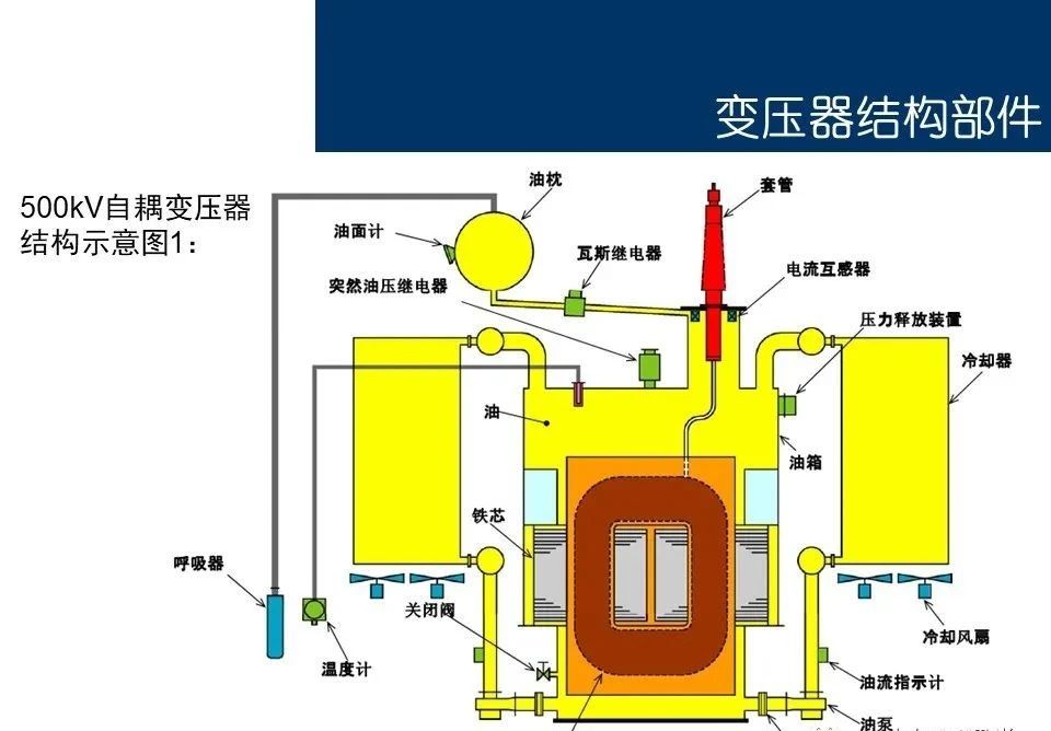
2. Structural Principles
2.1 Basic Operating Principle
Transformers operate on the principle of electromagnetic induction. When an alternating current (AC) flows through the primary winding, it generates a time-varying magnetic flux in the core. This flux induces an electromotive force (EMF) in the secondary winding, enabling voltage transformation.
- Key Equations:
- Voltage ratio: V2V1=N2N1
- Current ratio: I2I1=N1N2
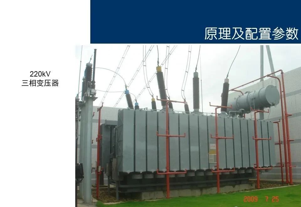
2.2 Transformer Types
Transformers are classified based on their application, construction, and voltage levels:
- By Application:
- Step-up transformers (increase voltage).
- Step-down transformers (decrease voltage).
- Distribution transformers (supply end-users).
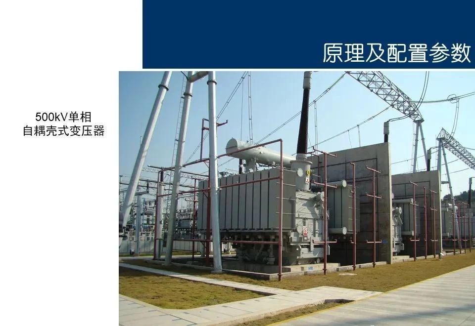
- By Construction:
- Core-type transformers.
- Shell-type transformers.
- By Cooling Method:
- Oil-immersed transformers.
- Dry-type transformers.
2.3 Tap Changers
Tap changers allow for voltage regulation by adjusting the turns ratio of the windings. They can be:
- On-Load Tap Changers (OLTC): Adjust taps while the transformer is energized.
- Off-Circuit Tap Changers: Require de-energization before adjustment.
3. Operation & Maintenance Essentials
3.1 Routine Inspection
Regular inspections are crucial to identify potential issues early and ensure safe operation. Key inspection points include:
- Oil level and quality (for oil-immersed transformers).
- Temperature monitoring (top oil temperature, winding hot-spot temperature).
- External components (bushings, radiators, fans, etc.).
3.2 Preventive Maintenance
Preventive maintenance activities aim to extend the transformer's lifespan and avoid unexpected failures:
- Oil Testing:
- Dissolved gas analysis (DGA) to detect incipient faults.
- Dielectric strength and moisture content testing.
- Insulation Resistance Measurement:
- Megger tests to assess insulation integrity.
- Winding Resistance Testing:
- Detects loose connections or winding damage.
3.3 Fault Diagnosis
Common transformer faults include:
- Overheating: Caused by overloading, poor cooling, or insulation degradation.
- Short Circuits: Internal winding faults due to insulation failure.
- Excitation Inrush Current: Temporary overcurrent during energization.
- Partial Discharge: Localized electrical discharges in insulation systems.
Advanced diagnostic tools such as infrared thermography, ultrasonic testing, and online monitoring systems are increasingly used for fault detection.
3.4 Emergency Response
In the event of a fault, immediate actions include:
- Isolating the transformer from the power system.
- Conducting root cause analysis (RCA) to identify the fault mechanism.
- Performing repairs or replacements as needed.
4. Emerging Trends and Innovations
4.1 Digitalization and Smart Monitoring
Modern transformers are equipped with sensors and IoT-enabled devices for real-time monitoring of parameters such as temperature, oil condition, and vibration. These systems enable predictive maintenance and enhance reliability.
4.2 Eco-Friendly Designs
Environmental concerns have led to the development of eco-friendly transformers:
- Use of biodegradable oils.
- Reduced use of hazardous materials.
- Improved energy efficiency to minimize losses.
4.3 Advanced Materials
New materials, such as amorphous metal cores and nanocomposite insulations, are being explored to improve efficiency and reduce losses.