With the rapid development of power systems, large-capacity high-parameter units have become widely adopted. When discussing transformer protection, excitation inrush current remains a perennial topic.
、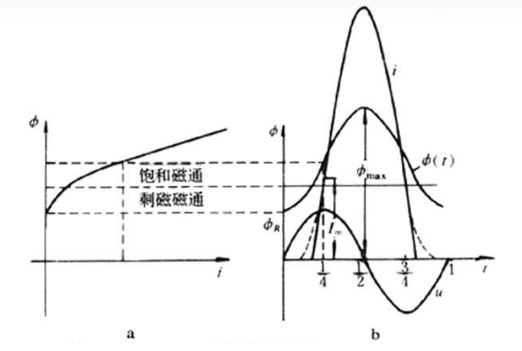
The relationship between the excitation current and the magnetic flux in transformer windings is determined by the magnetization characteristics. The more saturated the core becomes, the greater the excitation current required to produce a certain level of magnetic flux. During no-load energization or voltage recovery after external fault clearance, rapid energy conversion between electrical and magnetic fields causes a significant increase in core flux density, leading to severe core saturation. This reduces the excitation reactance significantly, causing a sharp increase in excitation current. The waveform of this current, determined by the magnetization curve, exhibits sharp peaks. This current is known as the excitation inrush current, which typically ranges from 5 to 10 times the rated current of the transformer and 50 to 100 times the no-load current, though it decays relatively quickly.
The excitation inrush current contains a significant non-periodic component, a large amount of higher harmonic components (primarily second harmonics), and exhibits a sharp-peaked waveform with discontinuities that are biased toward one side of the time axis.
The magnitude of the excitation inrush current depends on factors such as:
Generally, the larger the transformer capacity, the longer the decay duration, but the overall trend is that the decay rate of inrush current is slower than that of short-circuit current. The peak value of the excitation inrush current can reach 5 to 10 times the rated current.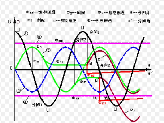
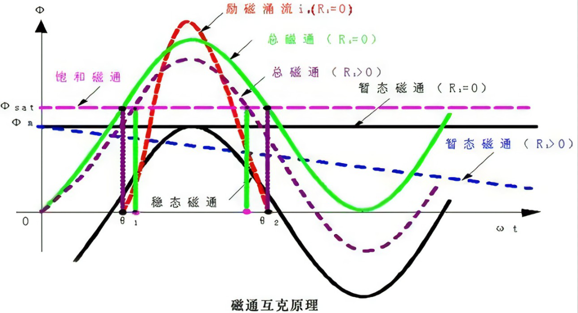
Under normal steady-state conditions, the magnetic flux in the core lags behind the applied voltage by 90° (the current through an inductor lags the applied voltage by 90°). If the circuit breaker closes at the instant when the voltage reaches its maximum value, the instantaneous value of the magnetic flux is zero, establishing a steady-state flux in the core. In this case, no excitation inrush current is generated.
However, if the circuit breaker closes at the instant when the voltage is zero, the magnetic flux established in the core reaches its maximum value (Φm). Due to the inability of the core flux to change instantaneously, the flux must remain zero initially. Consequently, a non-periodic flux component (Φfz) appears in the core, with an amplitude equal to Φm. The total flux in the core is the sum of these two components. At the start, the flux is zero, but after half a cycle (1/2 T), the two flux components add up to their maximum value, reaching 2Φ. Therefore, closing at the zero-crossing point of the voltage results in the most severe inrush current.
The magnitude and decay rate of the excitation inrush current depend on:
For three-phase transformers, due to the 120° phase difference between phases, at least two phases will exhibit different excitation inrush currents during any closing instant. This adversely affects the correct operation of differential protection, whereas it has minimal impact during steady-state operation or faults outside the differential zone.
Due to the complexity of power systems, transformers may experience voltage restoration without load disconnection. The presence of the load circuit, the magnetic flux state during fault occurrence and clearance, and the nonlinear characteristics of the core during transient processes result in unique electromagnetic transients during load-restoration inrush current.
There are generally two scenarios for load-restoration excitation inrush current:
During the fault period, the load-restoration excitation inrush current consists of two components:
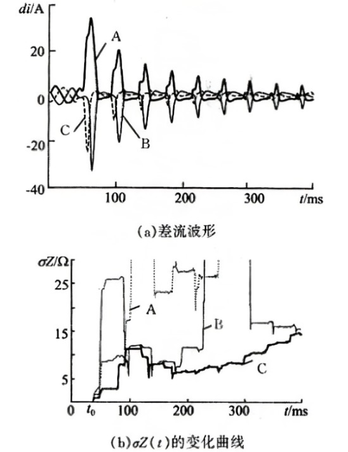
Analysis of differential current data on both sides of the transformer reveals the following characteristics of load-restoration inrush current:
Transformers exhibit core losses due to eddy currents and hysteresis. These losses can be represented by a parallel resistance in the equivalent circuit. However, since these losses are small, the parallel resistance is large and has minimal impact on inrush current decay, which can often be neglected.
Ignoring transformer and system losses and assuming Ls = Lσ = 0, the relationship for core flux Φ is given by:
Φ(θ) = Φp - Φm cos(θ), θ ≥ α
Where:
Let θJ.K represent the interruption angle of the k-th inrush current cycle:
θJ.K = θ2.K-1 + θ1.K
Transformer differential protection is based on the principle of steady-state magnetic balance. During transient processes, this balance is disrupted and only reestablished after the transient decays. A key challenge in differential protection is addressing maloperation caused by excitation inrush current. Commonly used inrush blocking methods include:
Excitation inrush current is the output current resulting from the superposition of steady-state and decaying DC flux acting on the nonlinear magnetization characteristics. In digital signal processing for protection, truncating the decaying DC component in time and performing periodic extension generates discrete amplitude spectra, which alias into the original spectrum and affect second-harmonic content. This poses challenges for differential protection using second-harmonic restraint.
Using fast-saturating current transformers blocks the transmission of excitation inrush current to the differential relay. When excitation inrush enters the differential loop, the highly saturable core of the fast-saturating current transformer rapidly saturates due to the large non-periodic component, sharply reducing the excitation impedance. This allows almost all non-periodic components and some periodic components of the inrush current to pass through the primary winding, while the secondary-side current remains very small, preventing differential protection from operating.
By appropriately adjusting the turns ratio of the fast-saturating current transformer’s primary and secondary windings, the impact of excitation inrush current on differential protection can be minimized.