The performance, efficiency, and reliability of a three-phase isolation transformer are heavily dependent on its winding design and material selection. These factors directly influence the transformer's ability to handle electrical loads, minimize losses, and operate safely under various conditions. Below, we provide a detailed technical analysis of these critical aspects.
1. Winding Design Considerations
The winding design of a three-phase isolation transformer is a complex process that involves determining the configuration, insulation, and physical arrangement of the windings. Key considerations include:
1.1 Primary and Secondary Winding Configurations
1.2 Layering and Interleaving Techniques
- Layered Windings:
- Windings are often arranged in layers to optimize magnetic coupling and reduce leakage inductance.
- Interleaved Windings:
- In high-performance transformers, interleaving primary and secondary windings minimizes flux leakage and improves efficiency.
1.3 Cooling and Thermal Management
- Proximity to Core:
- Windings closer to the core experience higher magnetic flux densities, which can lead to localized heating. Proper spacing and cooling channels are essential to manage temperature rise.
- Axial and Radial Ventilation:
- Cooling ducts and ventilation paths are integrated into the winding design to dissipate heat effectively, especially in high-capacity transformers.
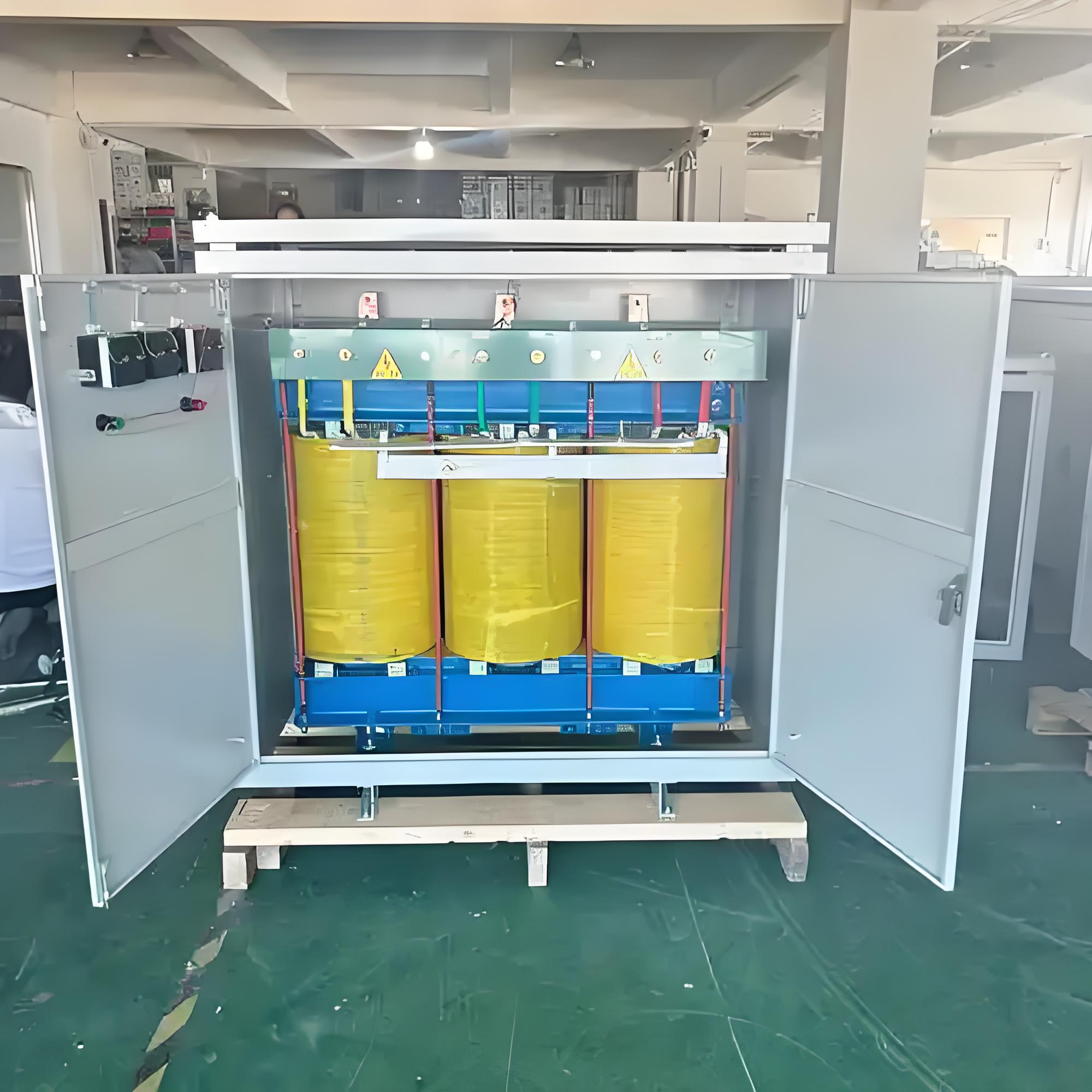
2. Material Selection for Windings
The materials used for the windings significantly impact the transformer's electrical and thermal performance. Key factors in material selection include conductivity, mechanical strength, and thermal stability.
2.1 Conductor Materials
- Copper Windings:
- Copper is the preferred material for most transformers due to its high electrical conductivity (∼58MS/m) and excellent thermal conductivity.
- Advantages:
- Low resistive losses (I²R losses).
- High durability and resistance to mechanical stress.
- Aluminum Windings:
- Aluminum is used in cost-sensitive applications but has lower conductivity (∼37MS/m) compared to copper.
- Advantages:
- Lower material cost.
- Lighter weight, making it suitable for portable or mobile applications.
- Disadvantages:
- Higher resistive losses and larger conductor cross-sections required.
2.2 Insulation Materials
3. Core Material Selection
While not part of the windings directly, the core material interacts closely with the winding design and influences overall transformer performance.
3.1 Magnetic Core Materials
3.2 Core Construction
- Laminated Cores:
- Thin laminations of silicon steel are stacked to reduce eddy current losses. Each lamination is insulated with a thin oxide or varnish coating.
- Tape-Wound Cores:
- Used in specialized applications where toroidal or C-shaped cores are required for compact designs.
4. Thermal Stability and Environmental Resistance
The materials used in winding and core construction must withstand environmental stresses such as temperature variations, humidity, and chemical exposure.
4.1 Thermal Stability
- Thermal Class Ratings:
- Transformers are rated based on their maximum allowable operating temperature (e.g., Class A: 105∘C, Class B: 130∘C, Class H: 180∘C).
- Temperature Rise Limits:
- The winding temperature rise is carefully controlled through proper material selection and cooling design to ensure long-term reliability.
4.2 Environmental Resistance
5. Advanced Design Techniques
Modern three-phase isolation transformers incorporate advanced design techniques to optimize performance and efficiency.
5.1 Foil Windings
- Foil conductors are used in some designs to reduce skin effect and proximity effect losses, particularly in high-frequency applications.
5.2 Resin Encapsulation
- Dry-type transformers often use resin encapsulation to provide additional protection against moisture, dust, and mechanical stress.
5.3 Finite Element Analysis (FEA)
- FEA tools are used to simulate electromagnetic fields, thermal distribution, and mechanical stresses during the design phase, ensuring optimal winding geometry and material utilization.